


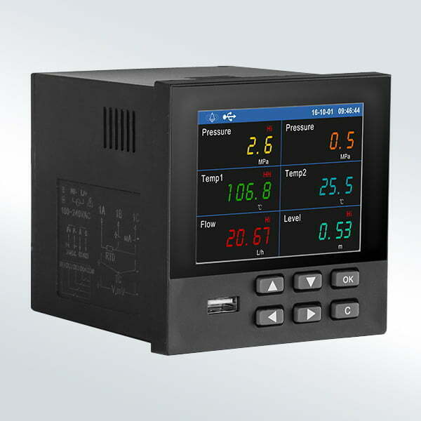
RK600-03 General Color Data Logger berisi pengumpulan sinyal, tampilan, pemrosesan, operasi, alarm, perekaman dan fungsi lainnya, dengan 18 saluran input sinyal analog, 4 output alarm relay, 150 mA kapasitas output daya (6 saluran dua transduser kawat atau 2 saluran empat kawat transduser), 1 antarmuka komunikasi RS485 dan 1 transfer data USB.
Produk ini mengadopsi kecepatan tinggi, kinerja tinggi 32-bit CPU (M4 mikroprosesor), PCB setelah “tiga perawatan pencegahan anti-korosi, kelembaban-bukti & debu-bukti”. Memiliki kemampuan anti-interferensi yang kuat.
Perekam dapat digunakan dalam metalurgi, meteorologi, perminyakan, industri kimia, bahan bangunan, kertas, listrik, makanan, farmasi dan pengolahan air industri dan industri lainnya.
FITUR

  * Layar LCD berwarna TFT
  * 18 input saluran analog
  * Perlindungan daya-gagal
  * Output RS485 (RTU) opsional
  * Dukungan alarm dan fungsi kontrol
  * Dengan penyimpanan eksternal 8G U-disk
SPECIFICATION
|
Item |
Details |
| Display |
3.5” TFT true color LCD display, 320 * 240 resolution, high-definition LED back-light, three side close to zero point of view |
| Input channels |
1-18 optional(signal type can be configured) |
| Input signal |
Current:4-20mA,0-10mA,0-20mA |
| Accuracy |
0.2%FS |
| Internal storage capacity |
48M |
| External storage |
U-disk(attached) |
| Supply |
AC220V,DC24V |
| Power consumption |
20VA(max.) |
| Operating temperature |
-10-+55℃@10-85%RH |
| Storage condition |
-20-+60℃@5-95%RH |
| Communication mode |
RS485(MODBUS-RTU),RS232(add external module) |
| Output capability |
3.6W(24V@150mA) |
| Sample Period |
1s |
| Power-drop protection |
Data stored in the internal flash, historical data and configuration parameters will not be lost when power supply drop |
| Alarm output |
Max.4 channels relay NO,250V/2A |
| Dimension |
96*96*100mm(hole size:92*92mm) |
| Installation of panel thickness |
1.5-6mm |
| Weight(unpacked) |
370g |
 Dimension

Unit:mm
MOUNTING

INPUT CONNECTION

CONFIGURATION INSTRUCTIONS
Input Settings
|
Configuration
Item |
Function Description |
Parameter range |
|
Channel |
Select set analog channel |
AI1~AI18 |
|
Bit |
Set bit of the analog channel |
Custom string’s length is 8 |
|
Unit |
Set the unit for analog channel |
Custom string’s length is 8 |
|
Signal |
Setting Signal Types |
(4~20) mA,( 0~20) mA,( 0~10)mA, |
|
Lower Range limit |
Set lower Range limit |
-99999~99999 |
|
Upper Range limit |
Set upper range limit |
-99999~99999 |
|
Correction factor A |
A in Y=A*X+B |
-99999~99999 |
|
Correction factor B |
B in Y=A*X+B |
-99999~99999 |
|
First-order filter |
First-order filter parameter |
0s,1s,2s,5s,10s,15s |
|
Disconnection display |
Displays the value of channel disconnection |
-99999~99999 |
|
Alarm setting |
Enter to alarm setting screen. |
|
Alarm setting
|
Configuration Item
|
Function Description |
Parameter range |
|
Higher alarm HH |
Higher alarm value |
-99999~99999 |
|
Higher alarm output |
Higher alarm output terminal |
None, DO1, DO2, DO3, DO4 |
|
High alarm Hi |
High alarm value |
-99999~99999 |
|
High alarm output |
High alarm output terminal |
None, DO1, DO2, DO3, DO4 |
|
Low alarm Lo |
Low alarm value |
-99999~99999 |
|
Low alarm output |
Low alarm output terminal |
None, DO1, DO2, DO3, DO4 |
|
Lower alarm LL |
Lower alarm value |
-99999~99999 |
|
Lower alarm output |
Lower alarm output terminal |
None, DO1, DO2, DO3, DO4 |
|
Return difference |
Alarm return difference |
-99999~99999 |
Note : Return difference prevents repeated alarm when the measures date fluctuates from the alarm point. Here is the example of high alarm and return difference.

Function setting
Communication Settings
Instrument Support host computer communication operation to achieve real-time monitoring.
|
Configuration Item
|
Function Description |
Parameter range |
|
Instrument address |
Modbus Device Address |
1~254 |
|
Baud Rate |
Communication speed |
1200,9600,57600,115200 |
|
Parity bit |
Communication verify |
No parity, odd parity, even parity |
|
Floating-point format |
Floating point format |
1234,2143,3412,4321 |
U disk operation
The instrument support U disk as an external storage media, which will save the historical data or various kinds of information to computer through U disk to permanently saved.
|
configuration Item
|
Function Description |
File format |
|
Save historical record |
|
|
|
Save all the data in the HDR |
Save all the data in the HDR format |
HDA(.HDA) |
|
Save all the data in the CSV |
Save all the data in the CSV format |
Text (.csv) |
|
Save all the data in the HDA |
Save all the data in the HDA format |
Text (.csv) |
|
Save the cumulative report |
Save all the cumulative report |
Text (.csv) |
|
Save the alarm information |
Save all the alarm information |
Text (.csv) |
|
Save the power-fail record |
Save all the power-fail record |
Text (.csv) |
|
Save the log record |
Save all the log record |
Text (.csv) |
|
Save the Instrument configuration |
Save the current instrument configuration |
CFG(.cfg) |
|
Read the instrument configuration |
Read instrument configuration in U disk |
|
Path to save:
The file of the instrument saved the corresponding file of U root directory whose name is [Instrument name].
File name:
|
File
|
Subdirectory |
File name |
|
History record |
/History |
H161009A.csv/ H161009A.hda |
|
Cumulative Report |
/Info |
A161009A.csv |
|
Alarm information |
/Info |
B161009A.csv |
|
Power-fail record |
/Info |
P161009A.csv |
|
Log records |
/Info |
L161009A.csv |
Note:
Initial letters H, A, B, P, L represent types of files.
The numbers represents the date on which you save the file.
The last letter can be one of the letter from A to Z. it represents that you can save one type of file up to 23times a day.
Clear operation
|
Configuration Item
|
Function Description |
|
Clear all the accumulated value |
|
|
Clear all the accumulated reports |
|
|
Clear the alarm information |
Clear all the alarm information |
|
Clear all the power-fail records |
Clear all the power-fail records |
|
Clear the log records |
Clear all the log records |
System Settings
|
Configuration item
|
Function Description |
Parameter range |
|
Supplier password |
Set supplier password |
000000~999999 |
|
Acquirer password |
Set acquirer password |
000000~999999 |
|
Instrument name |
Set instrument name |
Strings of 8 bytes |
|
System time |
Set system time |
|
|
Time format |
Set time format |
YY-MM-DD, DD-MM-YY, |
|
Recording |
Set recording interval |
1s,2s,5s,10s,15s,30s,1s,2s, |
|
Startup screen |
Set the default start up screen. |
Front Panel ,digital display screen, |
|
Cycle Time |
The screen displays the cycle time of grouping |
0s, 5s, 10s, 30s |
|
Atmospheric pressure MPa |
Set the Atmospheric pressure of the instruments |
-999999~9999999 |
|
Restore factory configuration |
Restore factory configuration |
|
PARAMETER SELECTIONTABLE
|
Remark |
Series |
Type |
Analog input |
Alarm output |
Communication |
Power output |
Supply |
|
|
RK |
|
|
|
|
|
|
|
|
|
|
600 |
|
|
|
|
|
|
|
|
|
|
03 |
|
|
|
|
|
|
|
|
|
|
01 |
|
|
|
|
1 input channel |
|
|
|
|
02 |
|
|
|
|
2 input channels |
|
|
|
|
… |
|
|
|
|
… |
|
|
|
|
18 |
|
|
|
|
18 input channels |
|
|
|
|
|
A0 |
|
|
|
Without relay output |
|
|
|
|
|
A1 |
|
|
|
With 1 relay output |
|
|
|
|
|
A2 |
|
|
|
With 2 relay output |
|
|
|
|
|
A3 |
|
|
|
With 3 relay output |
|
|
|
|
|
A4 |
|
|
|
With 4 relay output |
|
|
|
|
|
|
T0 |
|
|
Without Communication |
|
|
|
|
|
|
T2 |
|
|
With RS232(add external module) |
|
|
|
|
|
|
T4 |
|
|
With RS485 |
|
|
|
|
|
|
|
P0 |
|
Without power output |
|
|
|
|
|
|
|
P1 |
|
With power output |
|
|
|
|
|
|
|
|
A |
AC220V |
|
|
|
|
|
|
|
|
D |
DC24V |


